Maptitude Help / Surface Analysis Tools / Working with Three-Dimensional Maps
Working with Three-Dimensional Maps
Maptitude can create a three-dimensional (3D) map in a 3D View. 3D Views can be comprised of one or more of the following types of 3D layers:
- Surface Layers which are generated from a map or image draped over a 3D surface that is defined by a grid layer, such as a digital elevation model (DEM), or a point layer that has a field containing elevation values. These are similar to 3D maps in previous versions of Maptitude.
- Footprint Layers which are extruded from an area layer such as building footprints. Footprints Layers are a simple way to represent buildings in a 3D view where they display as prisms with height defined in an attribute field in the area layer. These are similar to 3D map prisms in previous versions of Maptitude.
- Model Layers which are point layers with information about model files, where each model would be a building, bridge, or other structure. Model files can be stored in various 3D formats.
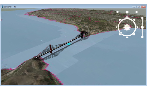
Maptitude uses the information in the 3D layers to create a 3D view. You can have any number of 3D layers in a 3D View and you can control which ones are visible. For example, the 3D view below has a surface layer made from a map of San Francisco and a model layer that contains a model of the Golden Gate Bridge.
Once you have created a 3D view, you can view it from various angles using tools in the 3D Tools toolbar. You can also move through your 3D view and visit particular viewpoints automatically using a flight path.
Any 3D Views that you have open in your workspace are saved as part of the workspace. When you close and reopen the workspace, your 3D Views will be restored.
About Surface Layers
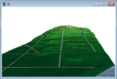 Surface layers in a 3D view require a point or grid layer in the map with a field containing elevation data. When you add a surface layer to a 3D view, you can specify the elevation units and apply an optional offset value.
For example, the 3D View to the right shows a map with a color theme on elevation and some roads. The 3D View uses elevation data in a hidden digital elevation model layer to drape the map over the surface elevation.
About Footprint Layers
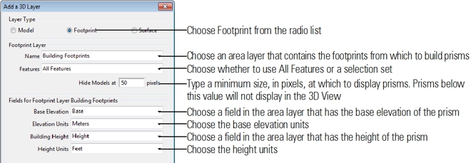
A footprint layers is created from an area layer in a map and is displayed in the 3D View as prisms. The area layer you use to create the footprint prisms requires two fields with the following data:
- Base Elevation: A field that contains the ground level elevation (i.e., the base of the prism)
- Building Height: A field that contains the height of the building (i.e., the height of the prism)
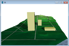 For example, the 3D View to the right shows a surface layer with an additional footprint layer. The base elevation value insures that each prism in the footprint layer is properly displayed on the surface, and not under or over it. The building height value determines the height of each prism.
If your area layer does not contain base elevation values, you can use the Tools>3D>3D Model Elevation Update command to automatically fill a field with elevation data from a point layer or digital elevation model.
 To Fill a 3D Footprint Area Layer Field with Base Elevation Values
- Open a map that contains the area layer to be used as a 3D Footprint Layer and a point layer that contains elevation data.
- Make the area layer the working layer.
- Choose Tools>3D>3D Model Elevation Update to display the 3D Model Elevation Update dialog box and make choices as follows:
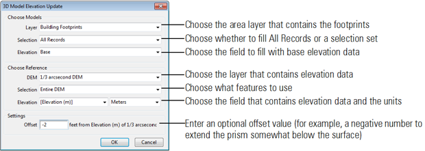
- Click OK.
Maptitude fills the chosen field with base elevation values.
About Model Layers
 Model layers are point layers with information about model files, where each model would be a building, bridge, or other structure. Maptitude supports models in several 3D formats:
- WRL: the format of the Virtual Reality Modeling Language (VRML)
- 3DS: the format of AutoDesk 3D Studio Graphics
- IV: the format of AutoDesk Inventor 3D
- SKP: the format of Trimble Sketchup
Model layers can have any number of data fields containing any data that you may have. In general, the fields in these layers and their contents are managed by Maptitude. When you use Maptitude to create a new model, the requisite model fields are created for you automatically. As you use the editing tools to add, move, scale, and rotate models, Maptitude automatically populates the fields with the data it needs to render the models as you have specified. Model layers will contain the following fields:
| Field | Description |
|---|---|
| Model File | The file name of the file containing the model |
| X Scale | The scale in the X dimension |
| Y Scale | The scale in the Y dimension |
| Z Scale | The scale in the Z dimension |
| X Rotation | The rotation in the X dimension |
| Y Rotation | The rotation in the Y dimension |
| Z Rotation | The rotation in the Z dimension |
| Rotation Angle | The angle of rotation |
| Center | A value of zero means the model coordinates are used as-is, a value of 1 means the coordinates are translated so the model is centered around the location where it is placed |
| Elevation | The elevation of the feature |
| Low Res. Model File | The optional file name of the file containing a low resolution version of the model |
| Low Res. Transition | The area in pixels at which to transition to the low resolution version of the model |
| Hide Transition | The area in pixels at which to hide the model |
Unless you already have a geographic file conveniently containing the point geographic locations of buildings, utilities or other objects that you wish to adapt and use as a model layer, you will typically not create or modify these fields on your own. If you do have such a geographic file, you will need to modify the attribute table to include the fields listed above.
About the 3D Tools Toolbar
The 3D Tools toolbar is a dockable toolbar that contains tools for moving around the scene in the 3D view window and for working with 3D models. You can toggle the toolbar on or off with the Tools>3D>3D Toolbar command. The controls are:
| Tool | Description |
|---|---|
 |
Tool to drag in any direction to see a different portion of the scene; you can also press the scroll wheel on the mouse to drag the scene when any tool is active |
 |
Tool to drag up (away) to zoom out to a smaller scale, or drag down (toward) to zoom in to a larger scale; you can also use the scroll wheel on the mouse to zoom in and out when any tool is active |
 |
Tool to tilt the scene up or down |
 |
Tool to rotate the scene clockwise or counter-clockwise |
 |
Button to return the 3D view to the initial scale; you can also right-click on the 3D view and choose Initial Scale when any tool is active |
 |
Button to save the current viewpoint in the 3D view as a bookmark or to change the viewpoint in the 3D view to that of a previously saved bookmark |
 |
Button to change the perspective in the 3D view to a viewpoint that matches a map window extent |
 |
Button to change the extent of a map window to match the current viewpoint in the 3D view |
 |
Tool to add a model |
 |
Tool to get information on a model |
 |
Tool to delete a model |
 |
Tool to move or scale a model |
 |
Tool to rotate a model |
 |
Button to choose the model to be added |
You can also use the controls that overlay the 3D view in the upper-right corner of the 3D window to move around the 3D view:
| To do this... | Do this... |
|---|---|
| Pan in one of the eight cardinal directions | Click the arrow in the direction that you want to pan the scene, or click and hold on the arrow to pan continuously. |
| Pan in any direction | Click and drag the eight-pointed shape in the middle of the circle in the direction that you want to pan the scene. Click and hold on the shape to pan continuously. |
| Rotate the 3D map | Click and drag the circle clockwise or counter-clockwise. The arrow on the circle indicates north. |
| Zoom into or out from the 3D map | Click and drag the dot on slider on the right side of the controls. Drag up to zoom in and drag down to zoom out. Zoom faster by dragging the dot farther up or down. |
| Tilt the 3D map up or down | Click and drag the dot on slider on top of the controls. Drag left to tilt up and drag right to tilt down. Tilt faster by dragging the dot farther left or right. |

The 3D window tries to maintain a viewpoint above the surface, although you can tilt the scene and view below the surface. It is important to keep in mind that models may have a base elevation that places them partially or fully below the surface, such as tunnels or other subsurface structures.
Creating a 3D View
A 3D View can contain one or more 3D layers. A simple 3D View may contain a single layer, such as a surface layer. A more complex one could also contain one or more footprint or model layers.
To Create a 3D View
- If your 3D View will contain a surface layer, open a map that contains a layer with elevation data. If your map will contain a footprint layer, open a map that contains an area layer of building footprints and a layer with elevation data.
- Choose Tools>3D>3D Map to display the Create 3D View dialog box.
If Maptitude detects a DEM layer in the map, it automatically adds a 3D Surface Layer that will display a snapshot of the map window. If Maptitude detects a DEM layer and an image layer, it automatically adds a 3D Surface Layer of the image file.
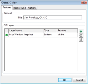
- Type a title for the 3D View in the Title box.
- To modify the 3D layers to display in the 3D View, make choices as follows:
| To do this... | Do this... |
|---|---|
| Add another 3D layer | Click  . Maptitude displays the Add a 3D Layer dialog box. To add a 3D Surface Layer, see the “Adding and Editing 3D Surface Layers” below. To add a 3D Footprint Layer, see “Adding and Editing 3D Footprint Layers” below. To add a 3D Model Layer, see “Adding and Editing 3D Models” below. . Maptitude displays the Add a 3D Layer dialog box. To add a 3D Surface Layer, see the “Adding and Editing 3D Surface Layers” below. To add a 3D Footprint Layer, see “Adding and Editing 3D Footprint Layers” below. To add a 3D Model Layer, see “Adding and Editing 3D Models” below. |
| Remove a 3D layer | Highlight one or more layers in the DataGrid and click  . . |
| Make layers hidden or visible | Click the symbol in the first column of the DataGrid.  indicates that a layer is visible and indicates that a layer is visible and  indicates a hidden layer. indicates a hidden layer. |
| Change the properties of a layer | Highlight the layer in the DataGrid and click  to display the 3D Layer Properties dialog box. Make changes to the properties and click OK. For more information on 3D Layer properties, see “Adding and Editing 3D Surface Layers,” “Adding and Editing 3D Footprint Layers,” or “Adding and Editing 3D Models” below. to display the 3D Layer Properties dialog box. Make changes to the properties and click OK. For more information on 3D Layer properties, see “Adding and Editing 3D Surface Layers,” “Adding and Editing 3D Footprint Layers,” or “Adding and Editing 3D Models” below. |
- To choose a sky and surface background, click the Background tab and choose one from the scroll list.
- Click the Options tab and make changes as follows:
| To do this... | Do this... |
|---|---|
| Change the position of the sun | Enter a date and time of day in the Based on Date, Time Zone, and Time of Day edit boxes. |
| Display shadows | Check the Shadows box. |
| Display fog or haze effects | Check the Fog box, choose a type (i.e., Fog, Haze, or Smoke) from the Type drop-down list, choose a color from the Color drop-down list, and enter a visibility in meters or feet in the Visibility Distance edit box. The visibility distance will control the thickness of the fog, haze, or smoke. |
| Exaggerate the elevations | Type a scaling value or use the arrows in the Exaggeration Factor spinner. |
- Click OK.
Maptitude displays the 3D view window with your chosen 3D layers. Maptitude also displays the 3D Tools toolbar. For more information on the 3D Tools toolbar, see About the 3D Tools Toolbar.
Adding and Editing 3D Surface Layers
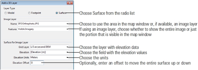
When you add or edit a 3D Surface Layer, you choose what portion of the surface to display and where the elevation data are stored.
To Add or Modify a 3D Surface Layer
- In the Create 3D View dialog box, click to add a Surface Layer or highlight a Surface Layer in the grid and click and make choices as follows:
- Click OK.
Maptitude adds the surface layer to the view or modifies the chosen surface layer.
Adding and Editing 3D Footprint Layers
When you add or edit a 3D Footprint Layer, you choose what layer to use to generate prisms in the 3D View and what fields contain the base elevation of the prisms and the prism height.
To Add or Modify a 3D Footprint Layer
- In the Create 3D View dialog box, click to add a Footprint Layer or highlight a Footprint Layer in the grid and click and make choices as follows:
 |
TIP: Maptitude can automatically fill in a base elevation field for you if you do not already have base elevation data. See To Fill a 3D Footprint Area Layer Field with Base Elevation Values for more information. |
- Click OK.
Maptitude adds the footprint layer to the view or modifies the chosen footprint layer.
Adding and Editing 3D Models
Generally, the 3D models that you use to build a 3D scene in Maptitude will be developed in another 3D modeling software package such as Trimble Sketchup or AutoDesk 3D Studio and exported or saved to one of the formats that Maptitude supports (e.g. .wrl, .3ds, .iv, .skp). You may create the models yourself or download them for free or purchase them over the web. The Trimble 3D Warehouse might be a useful resource for downloading models.
You add 3D models to a model layer in a 3D View and edit them using tools in the 3D Tools toolbar. When you add or move models in the 3D view, the point geography and attributes of the underlying model layer are simultaneously changed. When you scale or rotate a model, you may notice that the Scale and Rotation fields in the record of the corresponding point feature in the map are populated or adjusted. You will likely never have cause to review or modify any of these attributes directly, but in some rare cases, as discussed below, it may be useful to do so.
Note that manual updates in the model layer dataview are not reflected in an opened 3D view, but will take effect the next time a 3D view is opened or created.
About the Low Resolution and Hide Parameters
Very detailed models can overburden your video card, particularly when many detailed models are displayed in the scene at once. If you wish to work with highly detailed models or very large numbers of moderately detailed models, you may want to consider upgrading your video card. To improve performance, you can configure the low resolution and hide parameters for each model that you add. If you choose a low resolution model, it will appear in place of the more detailed, primary model when the primary model is far enough in the background that its pixel size drops below some threshold. Further, you can configure the model to be hidden when the model size in pixels drops below another threshold.
When you add a model to a model layer, the file name of the primary model is saved in the Model File field. If you also choose a low resolution model, its file name is saved in the Low Res. Model File field. If, in the opening or creation of a 3D view, you receive warning messages that a model file was not found, you should first confirm that the model file does exist, and then ensure that the model file name is correct. If the 3D View file was moved or the model files were moved such that the file names are no longer correct, you will need to update the file names in the dataview.
The pixel size threshold at which a model transitions to the low resolution model is saved in the Low Res. Transition field. The threshold at which the model is hidden is saved in the Hide Transition field. You might find it useful to adjust the values in these fields in the model layer dataview manually in order to refine these settings.
About Model Rotation
When you scale or move a model, you will notice that it is outlined in a rectangular bounding box that encloses the entire model. The orientation of this bounding box is dependent on how the model was created. Different 3D modeling software packages have different conventions, and may consider any one of the X, Y, or Z axes as pointing up or down. For this reason, when you add a model, you may find it is “rotated” on its side, upside down, or right side up, as expected. Unfortunately, there is no fixed standard to which all 3D modeling software adheres, so you may find that some models you have to rotate to make them upright after adding while others you do not. More commonly, for 3D models of buildings and other objects, you will probably need to rotate the model in the XY plane so that its footprint is aligned according to its true orientation.
The X Rotation, Y Rotation, Z Rotation, and Rotation Angle fields in the model layer are updated when you rotate a model. These fields are best left managed by the 3D Tools toolbar.
About Model Scale
As with the initial orientation of a model, its initial scale upon being added to a 3D view is dependent on the units of length in the model’s internal components. These could be any length unit. If you did not create the model yourself, you may need to consult the model’s author or the user manual of the software with which it was created in order to determine its model units. Often, however, the model units can be inferred based on the size of its bounding box. When you choose a model, Maptitude will display the size of this bounding box. Based on those dimensions, you may be able to easily determine the appropriate units. Note that the model units will determine the scale of the model when it is first added to a 3D view. You can then resize the model with the tools on the 3D Tools toolbar. Only one set of model units can be chosen. Thus, if you are using a low resolution model, you must ensure that its model units are the same as those of the primary model.
When you resize a model in a 3D view, the values in the X Scale, Y Scale, and Z Scale fields are updated. It is easiest to adjust a model’s size by scaling it with the 3D Tools toolbar, but on occasion you may find it useful to adjust the values in this field. The values store the ratio of the model’s internal dimensions to the 3D view dimensions in meters along the X, Y, and Z axes. For example, when a model whose model units are inches is added to a scene, the initial values in these fields is 0.0254, the conversion factor from inches to meters.
About Model Elevation
When you add a new 3D model to a model layer, it uses the position on the “ground” (zero elevation) where you click as a reference and places the model at some initial elevation, which you can specify when you choose the 3D model.
When you move a model with the 3D Tools toolbar, its elevation, saved in the Elevation field, may change. It is not possible to navigate beneath the ground surface in a 3D view. Thus, if you have models whose elevations are less than zero, they may appear partly buried in the ground or they may be hidden entirely beneath the surface. When this happens, it may be useful to manually change the value in the Elevation field in order to raise or lower the model appropriately. The units of the Elevation field are meters.
About Model Orientation
In some 3D software packages you may typically build the 3D object around the vertical axis such that the center of the model is positioned at (0, 0) in the horizontal plane. In other packages, you may build the model adjacent to the vertical axis such that one edge or corner of the model is at (0, 0) in the horizontal plane. Maptitude expects models to be centered around the vertical axis, and thus will place the model’s center at the position where you click in the 3D view. If the model is not centered at the vertical axis, then where you click in the 3D view is where the edge or corner of the model will be located. If you would like to have the model automatically centered when you place them in the 3D scene, you can indicate this preference.
To Create a New 3D Model Layer
- In the Create 3D View dialog box, click to add a Model Layer.
- Choose Model from the Layer Type radio list.
- Choose Create a New Model Layer from the Name drop-down list. Maptitude displays the Create a New Model Layer dialog box. Make choices as follows:

- Click OK. Maptitude creates a point layer with the necessary fields for storing model data.
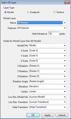
- Click OK.
Once you create the 3D View, you can use the tools in the 3D Tools toolbar to add models to the model layer.
To Add Models to a 3D Model Layer
- Create a 3D View that contains a model layer. If more than one model layer is in the 3D View, choose the model layer to use from the drop-down list on the Standard toolbar.
- If necessary, zoom, pan, or rotate the 3D View to display the location where you want to add a model.
- Click in the 3D Tools toolbar to choose the model to add. Make choices as follows:
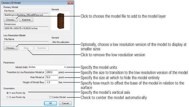
- Click OK.
- Click in the 3D Tools toolbar and click on the 3D View where you want to place the model.
Maptitude adds the model to the 3D view. Note that if the model units that were selected when the model was chosen are incorrect, the added model may be either too small to see or far too large. If this is the case, you may want to delete the model, click in the 3D Tools toolbar to reconfigure the units, and try again. If the scale of the model is close but not exactly correct, you may need to rescale it with move-and-scale tool (see below).
- Repeat steps 2-5 to add additional models to the 3D View.
- Click in the 3D Tools toolbar to activate the Scale and Move Model tool.
- Click on a model on the 3D View. Maptitude displays edit handles.
- Make choices as follows:
| To do this... | Do this... |
|---|---|
| Make the model taller or shorter | Click and drag a top or bottom middle edit handle up or down |
| Make the model thicker or thinner | Click and drag a middle side edit handle left or right |
| Make the model wider or narrower | Click and drag a middle front edit handle left or right |
| Make the model taller or shorter and thicker or thinner | Click and drag a top or bottom front corner edit handle |
| Make the model taller or shorter and wider or narrower | Click and drag a top or bottom side corner edit handle |
| Move the model around the 3D map | Click on a side between edit handles and drag the model to a new location |
If you drag the model so that all or part of the model is below an opaque surface, the lower part is hidden.
If you press Esc, you can undo all the scaling and moving done since you selected the model.
|
TIP: To move a model directly up or down parallel with the vertical edges of its bounding box, or to move it laterally parallel with one of the horizontal edges of its bounding box, hold the Shift key, then click between the edit handles on any side of the model having an edge parallel with the direction you want to move and drag parallel to that edge. |
- Click away from the model when you are done.
- Click in the 3D Tools toolbar to activate the Rotate Model tool.
- Click on a model on the 3D View. Maptitude displays X, Y, and Z rotation rings.
- Click and drag a rotation ring to rotate the model in the desired direction; the rotation ring that you are using turns yellow when you click on it.
If you press Esc, you can undo all the rotating done since you selected the model.
- Click away from the model when you are done.
To Get Information on a 3D Model
- Click in the 3D Tools toolbar to activate the Model Info tool.
- Click on a model on the 3D View. Maptitude displays the 3D Model Info dialog box.
- Click Close when you are done.
- Click in the 3D Tools toolbar to activate the Delete Model tool.
- Click on a model on the 3D View.
Maptitude displays a Confirm dialog box.
- Click Yes.
Maptitude deletes the model.
Try It Yourself: Creating a 3D Map
1. Choose File>Open Workspace or click  on the Standard toolbar, then open the San Francisco 3D workspace in the Tutorial folder. The map contains a digital elevation model, a JPEG image layer, and a point layer of 3D models.
2. Choose Tools>3D>3D Map to display the Create 3D View dialog box. Maptitude finds and lists the 3D Model Layer and a 3D Surface Layer that uses the image layer.
3. Click the first column in the 3D Buildings model layer to make the layer hidden.
4. Click the Background tab and choose Partly Cloudy from the scroll list.
5. Click OK. Maptitude creates a 3D view of the image layer draped on the elevations indicated in the digital elevation model and displays the 3D Tools toolbar.
6. Click on the 3D Tools toolbar and click and drag on the map to rotate the view. Notice the control in the upper right shows the direction of the view. Click and drag on the circle in the control to rotate the view some more.
7. Right-click on the 3D View and choose Properties.
8. Click the Features tab, click the first column in the 3D Buildings model layer to make the layer visible, and click OK. Maptitude adds the 3D model layer to the 3D View.
9. Click on the 3D Tools toolbar and click and drag on the 3D View to zoom in.
10. Click on the 3D Tools toolbar and click and drag on the 3D View to tilt the scene up or down.
11. Choose 3D Buildings from the drop-down list on the Standard toolbar.
12. Click on the 3D Tools toolbar then click on one of the models. Click and drag any of the editing handles to change the scale of the model. Click Esc when you are done to restore the original scale.
13. Click on the 3D Tools toolbar then click on one of the models. Click and drag one of the rings to rotate the model. Click Esc when you are done to restore the original position.
14. Choose File>Close Workspace and click Don't Save to close the workspace without saving any changes.
Managing 3D Views
After you have created a 3D View you can change most of its properties.
To Change the Properties of a 3D View
- Right-click on the 3D View window and choose Properties to display the 3D View Properties dialog box.
- Make changes on the Features, Appearance, Background, and Lighting tabs. See Creating a 3D View.
- Click OK.
Maptitude updates the 3D View.
|
TIP: You can also get to the 3D View Properties dialog box by clicking |
 on the Standard toolbar and then clicking
  in the Properties column of the 3D view you want to modify.
Tips for Developing 3D Models
Consider the tips below before you start creating complex, densely populated 3D Views.
A Single Model vs. Many Models
3D models do not necessarily represent singular, independent objects, such as a single building or bridge or park bench. They can be collections of objects, related or unrelated, near or far. For example, one 3D model file might contain an entire city block of buildings.
It is conceivable that you could put together the entire 3D scene in a 3D software package, and use that single model file in Maptitude. The smaller the area your 3D scene covers, the more attractive this approach may be. However, as your 3D area becomes larger, positioning a single 3D model containing a large number of objects spanning a large geographic area may become increasingly difficult. You lose the ability to shift or rotate independent buildings or other objects relative to others, and you may find it difficult to find exactly the right positioning, scale, and rotation that aligns accurately with the boundaries of your road segments.
Conversely, a separate model file for every single independent object in your 3D scene can be tedious to create, edit, and maintain. Thus, some balance between these two extremes is desirable. You may want to work with 3D models as logical and geographical clusters of objects located near one another.
A Single Layer vs. Many Layers
Recall that the 3D View is, like a map, a collection of geographic layers displayed together in the same window. You can hide and show layers in a 3D View just as you can in a map. This can be an incredibly powerful feature if you take advantage of it. When developing a 3D View, you may find it helpful to put like objects in the same layer. For instance, you may have a layer for building models, another for bridges, one for trees and plants, and so on. This way, you can hide and show layers selectively so that you can reduce the complexity of the 3D scene and navigate through it more easily as you add and edit models in each layer.
About 3D Model Complexity
It is important to keep model complexity in mind as you create 3D Views in Maptitude. Hugely detailed and complex models often offer no substantial visual benefit in a 3D View over lesser equivalents and can cause your 3D Views to become unmanageable. Consider a video card upgrade for your computer if you plan to do a lot of 3D modeling. Affordable video cards designed for gaming are widely available. A fast graphics processing unit (GPU) and ample video memory are desirable.
©2026 Caliper Corporation