Maptitude Help / Creating and Editing Geographic Files / Editing Line Features
Editing Line Features
You can only edit line layers that are in standard editable format, such as those that you create from scratch as described in Creating New Geographic Files. You cannot edit compact read-only format line layers such as those included in your Country Package (e.g., streets, railroads).
Lines have a starting point and an ending point, and they may also have any number of shape points in between. While you are adding or editing a line, the line is displayed with editing handles, like this:
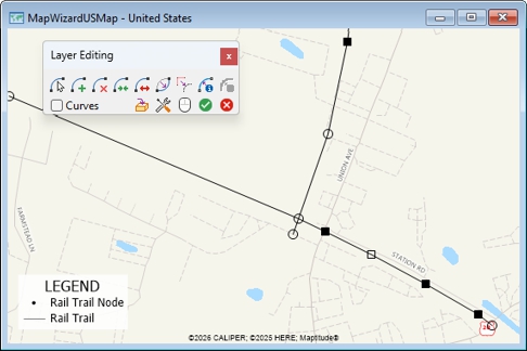
Endpoint editing handles are shown as empty black circles, shape point editing handles are shown as solid black squares, and an empty black square indicates a an editing point that is being edited.
A geographic file containing a line layer always has a second layer for the endpoints of the lines. You do not edit the endpoints directly. When you edit the lines, Maptitude keeps the endpoint layer up to date.
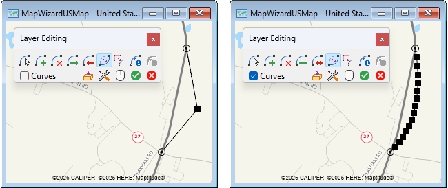
When you add or replace a line, you have the option of manually placing all of the shape points or using the Curves option. When you use the Curves option, Maptitude automatically inserts extra shape points between the points where you click. Here is an example:
When you add a line, you can choose whether or not to intersect it with any lines it crosses. If you choose to intersect new lines with existing lines, a new node will be added at every intersection, otherwise the intersections will be considered to be overpasses.
If you have set up a digitizer, you can switch to editing on the digitizer by clicking  in the Layer Editing toolbar. The button will change to
  to show that the digitizing tablet is now active. For more information on digitizers, see Using a Digitizer.
In this topic:
- Adding, Deleting, and Editing Line Features
- Editing Line Attributes
- Copying Values
- Copying and Pasting Segments
- Working with One-Way Streets
- Conflating Line Segments
- Simplifying and Smoothing Line Segments
Adding, Deleting, and Editing Line Features
You use the tools in the Layer Editing toolbar to add, delete, and edit line features:
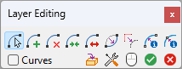
Here is a quick summary of the line editing tools and how they work:
| Tool | Name | Use it to... |
|---|---|---|
 |
Configure | Set up how new lines interact with existing ones, how many shape points to add to curves, and other basic settings; see To Configure Line Editing for more information |
 |
Add | Add new line segments to a layer; see To Add Lines for more information |
 |
Delete | Delete existing line segments from a layer; see To Delete Lines for more information |
 |
Modify | Move endpoints or shape points; see To Change the Shape of Lines for more information |
 |
Replace | Replace all of the shape points of a line segment while maintaining its endpoints; see To Replace the Shape Points of a Line for more information |
 |
Split | Split a line in two; see To Split a Line in Two for more information |
 |
Join | Join two lines together; see To Join Two Lines Together for more information |
 |
Edit Line Attributes | Edit values stored in one or more fields for a line segment; see To Edit Line Attributes for more information |
 |
Edit Node Attributes | Edit values stored in one or more fields for a node; see To Edit Node Attributes for more information |
 |
Smooth | Smooth a line by adding more shape points |
 |
Archive | Create a backup archive of the layer in its current state; see Archiving Geographic Files for more information on archiving and restoring from archives |
 |
TIP: You may want to make an archive before you begin editing and occasionally while you are editing to have backups. See Archiving Geographic Files for more information. |
 To Display the Layer Editing Toolbar for Editing Line Features
- Choose an editable line layer from the drop-down list on the Standard toolbar or create a new line layer as described in Creating New Geographic Files.
- If the Layer Editing toolbar is not visible, choose Tools>Editing>Layer Editing Toolbar to display it.
- When you are done editing features, choose Tools>Editing>Layer Editing Toolbar or click the Close button in the Layer Editing toolbar to close the toolbar.
- Click in the Layer Editing toolbar to display the Configure Geographic Editing dialog box.
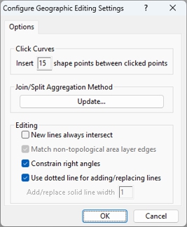
- Enter the number of shape points to be added when using the curves option in the Click Curves frame.
- To modify the aggregation method for fields click Update, make changes in the Aggregation Methods dialog box, and click OK. See To Change the Aggregation Method when Editing Map Features for more information.
- Check the New lines always intersect box to make intersection nodes wherever a new line crosses an existing one or leave it unchecked to treat crossing lines as underpasses/overpasses.
- Check the Constrain right angles box to make it easier to create right angles as shape points by constraining angles that are close to 90 degrees to exactly 90 degrees.
- Lines that you edit are shown with a dotted line by default. When editing over an image layer you may want to change the line style for better visibility by unchecking the Use dotted line for adding/replacing lines box and enter a width in pixels.
- Click OK.
Maptitude closes the Configure Geographic Editing dialog box.
| To do this... | Do this... |
|---|---|
| Have shape points lie along curves | Check Curves |
| Add each shape point without curves | Remove the check from Curves |
- Activate the Add tool in the Layer Editing toolbar by clicking on it.
- Click at the starting point of the line.
- To add one or more shape points, move the mouse to the next point and click. Right-click to back up.
- To end the line, press Enter or double-click on the endpoint. Maptitude displays the line with editing handles at the endpoints and shape points.
- Click
 to save your edits, or click
  to cancel.
If you saved your edits, Maptitude draws the map with the added lines. If you start or end a line near the starting or ending point of any other line in the layer, Maptitude makes sure that the lines meet.
- Click in the Layer Editing toolbar to activate the Delete tool.
- Click on each line you want to delete. Maptitude marks each deleted line in red.
- Click to save your edits, or click to cancel.
If you saved your edits, Maptitude draws the map without the deleted lines.
- Click in the Layer Editing toolbar to activate the Modify tool.
- Click on a line you want to modify. Maptitude displays editing handles at the endpoints and shape points.
- Edit the line according to the table:
| To do this... | Do this... |
|---|---|
| Move an endpoint | Drag it to a new location |
| Add a shape point | Click anywhere on the line |
| Delete a shape point | Click on a shape point and press the Delete key or drag the shape point onto an adjacent shape point |
- Click to save your edits, or click to cancel.
If you saved your edits, Maptitude draws the map with the lines in their new shapes. If you move the endpoint of a line, other lines that end at the same place will be changed automatically. Maptitude will display these lines with editing handles, too, so you can tell that you’ve changed them.
To Replace the Shape Points of a Line
- Choose how the shape points will be replaced:
| To do this... | Do this... |
|---|---|
| Have shape points lie along curves | Check Curves |
| Add each shape point without curves | Remove the check from Curves |
- Click in the Layer Editing toolbar and click on a line. All existing shape points are deleted.
- Add more shape points as follows:
| To do this... | Do this... |
|---|---|
| Add shape points | Click at the points |
| Remove the previous shape point | Click the right mouse button |
| Add the last shape point | Double-click on the last (or only) shape point |
- To replace other lines, return to Step 2.
- Click to save your edits, or click to cancel.
If you saved your edits, Maptitude draws the map with the replaced lines.
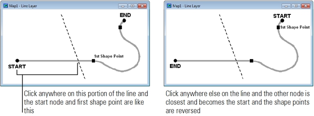
The Replace Line tool assumes a start and an end point. The start point is automatically chosen when you click on the line, and it is the node closest to where you clicked. The first shape point is connected to the start point. For example:
Try It Yourself: Editing Line Features, Part 1
1. Choose File>New Workspace, choose the New map of {country name} option, and click OK to start Create-a-Map Wizard and make a map of the state/county/province where you live.
2. Choose Tools>Editing>New Layer. Maptitude displays the New Layer dialog box.
3. Choose the Line Layer radio button, type “My Lines” as the layer name, and click OK.
4. Click OK again to close the Attributes dialog box without making changes. Maptitude adds the new line layer to the map and displays the layer editing tools.
5. At the bottom of the Display Manager, click the style sample next to "My Lines" and change the style to something that stands out a little more (for example change the width to 3pt and the color to dark blue), and click OK.
6. Click in the Layer Editing toolbar to activate the Add Line tool, then click at several points on the map. Maptitude displays a dashed line.
7. Click the right mouse button. The last shape point is deleted.
8. Double-click to end the line. Draw several more lines, including some that start where other lines end.
9. Click to save the lines. Maptitude draws them in the style for the layer.
10. Click to activate the Delete Line tool and click on one of the lines. The line turns red to indicate that it will be deleted.
11. Click to cancel the edit. The line is not deleted.
12. Click to activate the Modify Line tool and drag some endpoints and shape points to new spots.
13. Click on a line away from any existing points to add a new shape point, and drag it to a new spot.
14. Click on a shape point to choose it. Press the Delete key to delete that shape point.
15. Click to save the edits. Maptitude redraws the lines with the changes.
16. Leave the map as it is for Part 2 of this tutorial.
- Click in the Layer Editing toolbar to activate the Split tool.
- Click on the line where it is to be split. Maptitude splits the line into two separate lines and adds an endpoint, or if you clicked at a shape point, Maptitude changes the shape point to an endpoint.
- Click to save your edits, or click to cancel.
If you saved your edits, Maptitude draws the updated map.
To Split Lines Apart Where They Meet
When several lines meet at a common endpoint, you can use the Split tool to separate them so they don’t end at the same location.
- Click in the Layer Editing toolbar to activate the Split tool.
- Click on an endpoint where two or more lines meet. Maptitude displays editing handles on the lines and splits the endpoint into a separate endpoint for each line, so the lines no longer meet.
- Click to save your edits, or click to cancel.
If you saved your edits, Maptitude draws the updated map.
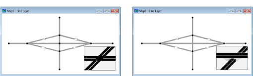
You can use this feature, along with the Join tool described below, to change an intersection to an overpass. Split the lines at the common endpoint in the center, then join the two North-South lines and the two East-West lines.
- Click in the Layer Editing toolbar to activate the Join tool.
- Click on an endpoint where two lines meet. Maptitude changes the endpoint to a shape point and joins the two lines. Editing handles are displayed on the new line.
- Click to save your edits, or click to cancel.
If you saved your edits, Maptitude draws the map with the lines joined together.
To Make Sure Two Lines Meet at a Common Point
Two lines meet only when they have a common endpoint. To make sure they meet, follow the steps below:
- Click in the Layer Editing toolbar to activate the Modify tool.
- Select two or more lines by clicking on them. Editing handles are displayed at the endpoints and shape points of all the lines you select.
- If the lines cross each other, click on the point where they cross to add an endpoint and split both lines in two. If the lines don’t cross, drag any point of one line so it is on top of any point on the other line, and drop it there. Maptitude changes that point to an endpoint and splits both lines in two.
- Click to save your edits, or click to cancel.
If you saved your edits, Maptitude draws the map with the lines updated.
Try It Yourself: Editing Line Features, Part 2
1. If you did not do Part 1 of this tutorial, go back and do it now.
2. Click in the Layer Editing toolbar, then add two new lines, with the second line starting where the first line ends.
3. Click then click on the endpoint where the two lines meet. Maptitude joins the two lines, changing the endpoint to a shape point. Click to save the edits.
4. Click then click on the line. Maptitude splits the line in two with a new endpoint where you clicked.
5. Click again on the same point. Maptitude moves the endpoints of the two lines apart so they no longer meet.
6. Click then pick up either endpoint and place it on the other. Maptitude connects the two lines. Click to save the changes.
7. Click then add two new lines that cross in the middle in the shape of an X.
8. Click and then click on the point where the two lines cross. Maptitude splits the lines. Drag the new endpoint to see how the lines are connected.
9. Click and click on the new endpoint. Maptitude splits the lines apart. Click to save the changes.
10. Click in the toolbar to activate the Replace Line tool and make sure the Curves box is not checked.
11. Click on one of the lines, click several times to add shape points to the line, and double-click at the last point. Click to save the changes.
12. Check the Curves box and click on the same line. Move the cursor to display a curved dashed line and double-click. Maptitude creates a curve with several shape points. Click to save the changes.
13. Choose File>Close Workspace and click Don't Save to close the workspace without saving any changes.
Editing Line Attributes
The Edit Line Attributes and Edit Node Attributes tools help you to display and edit attributes for one or more lines or nodes. The attributes are displayed in an Edit Attributes window. You can choose which fields are displayed by creating field sets, and you can edit and copy values from the highlighted features to other features in the Edit Attributes window.
The edits to line attributes are stored in the map editing buffer and are not saved until you click to save edits. If you click to cancel edits, all pending attribute (and geographic) edits will be discarded. Clicking either button will also close the Edit Attributes window.
- Click in the Layer Editing toolbar to activate the Edit Line Attributes tool.
- Select the line or lines to display in an Edit Attributes window as follows:
| To do this... | Do this... |
|---|---|
| Select one line | Click on the line. Maptitude displays the line in the Edit Attributes window. |
| Select more lines | Hold the Shift key and click on the lines. Maptitude adds the lines to the Edit Attributes window. |
| Deselect lines | Hold the Ctrl key and click on the lines. Maptitude removes the lines from the Edit Attributes window. |
The last line selected has its ID field highlighted in the Edit Attributes window. To make sure you are about to edit the correct line, hold the Shift key and click on that line.
- Make changes as follows:
| To do this... | Do this... |
|---|---|
| Replace a value in a cell | Click on the cell and type a new value. |
| Edit a value in a cell | Double-click on the cell and change the value. |
| Choose a field set | Right-click and choose Field Sets to display the Field Sets dialog box. Highlight an existing field set or create a new field set, and click OK. |
| Replace values in a range of cells | Right-click in one cell, drag to another cell to highlight a range of cells, and choose Fill to display the Fill dialog box. Choose a fill method, enter the necessary values, and click OK. |
| Copy values to other selected records | Right-click on a column heading or a cell in a record and choose Copy Values to display the Confirm dialog box. Click OK to copy the values from the highlighted record to the other selected records. |
- To edit attributes for other lines, return to Step 2.
- Click to save your edits, or click to cancel.
Maptitude updates the attributes for the lines and displays the map with any changes.
If the node layer for a line geographic file has attributes, the Edit Node Attributes tool will be enabled. If the node layer is hidden, the tool will still be able to select nodes. If the node layer has been dropped from the map, Maptitude will prompt you to add the layer to the map.
- Click in the Layer Editing toolbar to activate the Edit Node Attributes tool.
- Select the node or nodes to display in an Edit Attributes window as follows:
| To do this... | Do this... |
|---|---|
| Select one node | Click on the node. Maptitude displays the node in the Edit Attributes window. |
| Select more nodes | Hold the Shift key and click on the nodes. Maptitude adds the nodes to the Edit Attributes window. |
| Deselect nodes | Hold the Ctrl key and click on the nodes. Maptitude removes the nodes from the Edit Attributes window. |
The last node selected has its ID field highlighted in the Edit Attributes window. To make sure you are about to edit the correct node, hold the Shift key and click on that node.
- Make changes as follows:
| To do this... | Do this... |
|---|---|
| Replace a value in a cell | Click on the cell and type a new value. |
| Edit a value in a cell | Double-click on the cell and change the value. |
| Choose a field set | Right-click and choose Field Sets to display the Field Sets dialog box. Highlight an existing field set or create a new field set, and click OK. |
| Replace values in a range of cells | Right-click in one cell, drag to another cell to highlight a range of cells, and choose Fill to display the Fill dialog box. Choose a fill method, enter the necessary values, and click OK. |
| Copy values to other selected records | Right-click on a column heading or a cell in a record and choose Copy Values to display the Confirm dialog box. Click OK to copy the values from the highlighted record to the other selected records. |
- To edit attributes for other nodes, return to Step 2.
- Click to save your edits, or click to cancel.
Maptitude updates the attributes for the nodes and displays the map with any changes.
Copying Values
When you are using the Edit Attributes window, you can copy values from one record to all other records displayed in the Edit Attributes window. You can copy values for all fields, or just those in the chosen field set.
To Copy Values
- Choose the record from which you are copying values, and the records to which you want to copy values, with the Edit Line Attributes tool or Edit Node Attributes tool .
- If you want to copy values from only certain fields, use field sets as described in Creating and Using Field Sets.
- Right-click on a cell, a range, or a column heading in the Edit Attributes window to highlight the record that will be the source for the values, and choose Copy Values. Maptitude displays a Confirm dialog box, indicating the number of records that will be filled with new values.
- Choose Yes to fill the other records with the values from the highlighted record, or No to leave the values unchanged.
Copying and Pasting Segments
You can copy segments from one line layer and paste them into another with the tools in the Copy & Paste toolbar. If you have a line layer that needs updating, you can get the missing segments from another line layer. You paste the segments into the target layer, which must be an editable geographic file. You copy the segments from the source layer, which can be a compact geographic file.
You can move data from the source layer to the target layer, by indicating the source field to use for each target field. For handling new endpoints, you have considerable control over:
- The distance within which an endpoint of a source segment will be snapped to an existing target endpoint
- Whether an existing target segment should be split if an endpoint of a pasted segment is within the snap distance of the target segment, but not within the snap distance of a target endpoint
- Whether a new target endpoint should be created if it is not within the snap distance of an existing target segment or endpoint
To Copy and Paste Segments
- Choose or create a map that has at least two line layers.
- Choose the target layer from the drop-down list on the Standard toolbar. The geographic file for the target layer must be editable.
- Choose Tools>Editing>Copy & Paste>Copy & Paste Lines. Maptitude displays the Choose Layers dialog box.
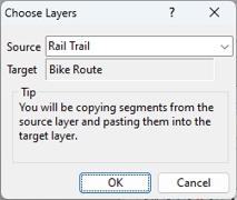
- Choose the source layer from the Source drop-down list.
- Click OK to display the Configure Settings dialog box.
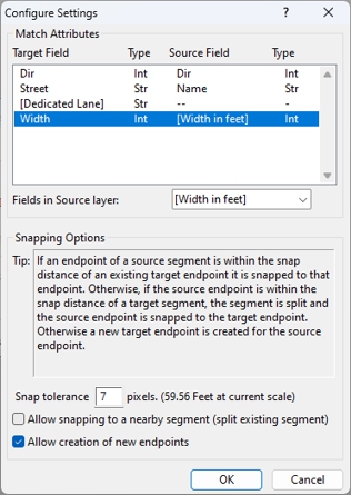
- Make changes to the settings as follows:
| To do this... | Do this... |
|---|---|
| Copy data to the target line layer | Highlight a target field in the Match Attributes scroll list and choose a field from the Fields in Source Layer drop-down list. Choose None to not copy data into a target field. |
| Set the snap tolerance | Type a value in the Snap Tolerance edit box. Once you press Tab or use another control the new distance will be displayed in map units. |
| Allow the splitting of existing segments | Check the Allow Snapping to a Nearby Segment box or uncheck to prevent splitting. |
| Create new endpoints | Check the Allow Creation of New Endpointsbox or uncheck to prevent the creation of new endpoints. |
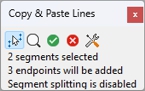
- Use the tools in the toolbar as follows:
| To do this... | Do this... |
|---|---|
| Select source segments to be copied | Click the Select Source Segments tool  to activate it and click on the first segment. Press the Shift key and click on any additional segments. Press the Ctrl key and click on selected segments to deselect them. The number of selected segments is displayed in the toolbar. Once at least one segment is selected the Find Target Placement to activate it and click on the first segment. Press the Shift key and click on any additional segments. Press the Ctrl key and click on selected segments to deselect them. The number of selected segments is displayed in the toolbar. Once at least one segment is selected the Find Target Placement  button is enabled. button is enabled. |
| Check to see how the segments will be pasted | Click Find Target Placement . The numbers of endpoints that will be added and segments that will be split are displayed in the toolbar. If the paste can be done, Paste New Segments and Cancel New Segments are enabled. |
| Change the settings that will be used | Click Configure and return to step 5 to change the settings. If you change any settings, Find Target Placement will be disabled and you will need to recheck to see how the segments will be pasted. |
- Click Paste New Segments to paste the segments, or Cancel New Segments to cancel pasting the segments. Both buttons clear the selected segments. Return to step 7 to select additional segments to paste.
- Choose Tools>Editing>Copy & Paste>Copy & Paste Lines or click the close button in the top right corner of the toolbar.
Maptitude closes the toolbar. Any pending changes are ignored.
Working with One-Way Streets
If your line layer contains one-way streets, Maptitude uses this information automatically in its analysis. For example, the HERE street layer included with your Country Package includes information on one-way streets that Maptitude will consider when finding shortest routes, solving traveling salesman problems, or determining drive-time rings.
Marking One-Way Streets
If you are working with your own street file or other line layer in a standard (.dbd) format, you can easily mark streets as one-way or two-way. Simply select the streets you want to mark using any of the selection tools or commands, and then use the Tools>Editing>One Way Line Segments command to designate streets as one-way in any compass direction, or as two-way. You cannot mark one-way streets in a compact, read-only geographic file (.cdf). For more information, see Geographic File Formats.
To Mark Streets as One-Way or Two Way
- Select the streets you want to mark using any of the selection tools or commands.
- Choose Tools>Editing>One Way Line Segments do display the Update Direction dialog box.
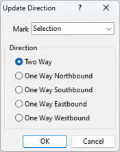
- Choose the selection set that contains the streets that you want to change from the Mark drop-down list.
- Choose Two Way from the radio list to mark the selected streets as two-way or choose the one-way compass direction that best indicates the permitted direction of travel to make the selected streets as one-way.
- Click OK.
Maptitude updates the streets.
Displaying One-Way Streets
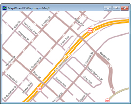
Maptitude uses arrowheads displayed on each line feature to show the location of one-way streets. For example, the map below shows one way streets and highway ramps with arrowheads indicating the direction of travel.
- If the Display Manager is not visible, choose Map>Display Manager Toolbar.
- Click the style sample of the line feature you want to modify to display the Style dialog box.
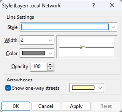
- Check the Show One-Way Streets box and choose a color for the arrow from the drop-down list.
- Click OK.
From now on, Maptitude shows arrowheads on one-way streets.
 |
NOTE: The street layer that is included with Maptitude uses feature display settings to display different types of streets with different styles. To see one way streets on the streets layer, you will need to change the feature display setting styles instead of the layer style. For more information, see Using Feature Display Settings. |
Conflating Line Segments
You use the conflate tools to interactively reshape the segments in a line layer to align with a more accurate line layer. For example, you may create a line layer that contains one or more bus routes and you want to align them with the Maptitude street layer.
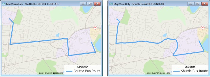
Before conflating, the shuttle bus route does not align with the streets (left). After conflating, the shuttle bus route aligns with the streets (right)
The target layer contains the segments that you want to reshape (e.g., bus routes) and it must be an editable geographic file that is either stored in the workspace or is in standard DBD format. The source layer contains the more accurately shaped segments and nodes (e.g., Maptitude street layer). You can choose whether the endpoints of the target segment should be snapped to the source segment endpoints as well.
|
NOTE: The endpoint node layer of the source and target layers will be automatically displayed when you conflate. You can hide the node layers when you are done conflating. |
There are two ways to identify the target and source segments:
- Select a set of segments with the Select the Target Segments tool
 or Select the Source Segments tool
 - Have Maptitude find the segments on the shortest path between the nodes you specify
You can limit the shortest path to segments that have matching values in fields that you choose, such as the segment name field in each line layer. You can also choose to add conflated links to a selection set so that you can keep track of which links have been completed.
 To Conflate Segments
- Choose or create a map that has at least two line layers.
- Make the target layer the working layer either by choosing it from the drop-down list on the Standard toolbar or right-clicking on it in the Display Manager and choosing Make Working Layer. The geographic file for the target layer must be editable.
- Choose Tools>Editing>Conflate Line Segments. Maptitude displays the Choose Layers dialog box.
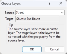
- Choose the source layer from the drop-down list and click OK. Maptitude displays the Conflate Line Segments tools.
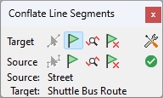
- Click to display the Configure Settings dialog box and make choices as follows:
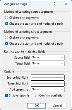
- Choose how to select the source and target segments from the two radio lists. Choose Click to pick segments if you want to click on individual segments to pick them or choose Choose the start and end nodes of a path if you want to pick segments using a shortest path between two nodes.
- To restrict a shortest path to segments that have matching fields, such as name, choose the fields that contain the values to match from the Source field and Target field drop-down lists.
- Click the highlight samples to change how source and target segments appear when selected.
- Optionally, choose a selection set to which to add conflated target links from the Add targets to drop-down list.
- Check the Snap endpoints box to snap target nodes to the source nodes.
- Check the Confirm conflation box to display a Confirm dialog box before making changes.
- Click OK when you are done.
- Choose the target segments to conflate as follows:
| If you chose the... | Do this... |
|---|---|
| Pick segments method | Click and click on the first segment to conflate. Press the Shift key and click on any additional segments. Press the Ctrl key and click on selected segments to deselect them. |
| Choose the start and end nodes of a path method | Click  and click on two or more nodes. Click and click on two or more nodes. Click  to select the segments along the shortest path. Click to select the segments along the shortest path. Click to clear the selected nodes and segments and start over with new nodes. to clear the selected nodes and segments and start over with new nodes. |
- Choose the source segments as follows:
| If you chose the... | Do this... |
|---|---|
| Pick segments method | Click and click on the first source segment. Press the Shift key and click on any additional segments. Press the Ctrl key and click on selected segments to deselect them. |
| Choose the start and end nodes of a path method | Click and click on two or more nodes. Click to select the segments along the shortest path. Click to clear the selected nodes and segments and start over with new nodes. |
- Click . Maptitude may display one or more Confirm dialog boxes to indicate what is about to happen. Click Yes to continue the conflation process. Maptitude conflates the target segment to the source segment or segments. Return to step 6 to conflate another segment.
- Choose Tools>Editing>Conflate Line Segments or click the close button in the top right corner of the toolbar.
Maptitude closes the toolbar. Any pending changes are ignored.
Try It Yourself: Conflating Line Features
1. Choose File>New Workspace, choose the New map of {country name} option, and click OK to start Create-a-Map Wizard and make a map of your ZIP Code or postal code.
2. Choose Tools>Editing>New Layer. Maptitude displays the New Layer dialog box.
3. Choose the Line Layer radio button, type “My Bus Route” as the layer name, and click OK.
4. Click OK again to close the Attributes dialog box without making changes. Maptitude adds the new line layer to the map and displays the layer editing tools.
5. At the bottom of the Display Manager, click the style sample next to "My Bus Route" and change the style to something that stands out a little more (for example change the width to 4pt and the color to dark blue), and click OK.
6. Click in the Layer Editing toolbar to activate the Add Line tool, then click at one end of any fairly winding street and double-click at the other end, then click to save the straight line bus route.
7. Choose Tools>Editing>Conflate Line Segments, choose Street from the Source drop-down list, and click OK.
8. Click to display the Configure Settings dialog box, choose the Choose the start and end nodes of a path option from the first radio list of source segment methods, choose Click to pick segments from the second radio list of target segment methods, and click OK.
9. Click and click on the Bus Route line you just added.
10. Click and click on the intersections in the street layer that correspond to the end points of the bus route.
11. Click and click . Maptitude conflates the bus route line to the street layer.
12. Choose File>Close Workspace and click Don't Save to close the workspace without saving any changes.
Simplifying and Smoothing Line Segments
If your line segments have many redundant shape points or not enough to make the line appearance smooth, you can use the Tools>Editing>Line Simplify/Smooth Toolbar command to display the Simplify toolbar. The toolbar contains the following tools:
| Tool | Name | What it does |
|---|---|---|
 |
Simplify | Removes unnecessary shape points |
|
Smooth | Smooths a line by adding more shape points |
 |
Trim Kinks | Removes shape points that form kinks near the end of a line |

Simplify the line on the left to get the result on the right

Smooth the line on the left to get the result on the right

Remove kinks from the line on the left to get the result on the right
You have the option of using the tools on a single line segment at a time or you can click  and use the Configure Line Simplify/Smooth Tools dialog box to smooth, simplify, or trim a selection set of line features or an entire line layer.
To Configure the Simplify/Smoothing/Trim Kinks Tools
- Choose an editable line layer from the drop-down list on the Standard toolbar.
- Choose Tools>Editing>Line Simplify/Smooth Toolbar to display the Simplify toolbar.
- Click to display the Configure Line Simplify/Smooth Tools dialog box.
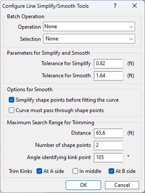
- Make change to any of the options:
| Option... | What it does... |
|---|---|
| Tolerance for Simplify | Defines the maximum distance allowed when removing a shape point. If there are three shape points that are nearly colinear and the distance from the second point to the line between the first and third points is less than the tolerance, then the second point will be removed. |
| Tolerance for Smooth | If the distance from a shape point to its neighbor points is smaller than this tolerance then these points are kept as they are; otherwise additional shape points are inserted to make the line smoother. |
| Simplify shape points before fitting the curve | Removes unnecessary shape points before a line is smoothed. |
| Curve must pass through shape points | Preserves all existing shape points when smoothing. |
| Distance | Determines how far inside a line to search for kink points. If a kink point is found within the specified distance and number of shape points, that point, along with all the shape points between it and the end point are deleted in order to remove the kink. |
| Number of shape points | Determines how many shape points from the endpoint to search for kink points. If a kink point is found within the specified number of shape points and distance, that point, along with all the shape points between it and the end point are deleted in order to remove the kink. |
| Angle identifying kink point | 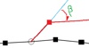 The angle at which a point is considered a kink point. If the angle to the next line section is greater than or equal to this threshold it is considered a kink point. The angle at which a point is considered a kink point. If the angle to the next line section is greater than or equal to this threshold it is considered a kink point. |
| A side | Check to trim kinks at the topological start of the line |
| In middle | Check to trim kinks anywhere in the line |
| B side | Check to trim kinks at the topological end of the line |
- Click OK.
To Simplify a Line by Pointing
- Choose an editable line layer from the drop-down list on the Standard toolbar.
- Choose Tools>Editing>Line Simplify/Smooth Toolbar to display the Simplify toolbar.
- Click the Simplify tool to activate it.
- Click on a line segment.
Maptitude simplifies the line by removing shape points that are within the simplify tolerance.
To Batch Simplify a Selection Set of Lines or an Entire Line Layer
- Choose an editable line layer from the drop-down list on the Standard toolbar. Optionally select the line features that you want to simplify.
- Choose Tools>Editing>Line Simplify/Smooth Toolbar to display the Simplify toolbar.
- Click to display the Configure Line Simplify/Smooth Tools dialog box.
- If you selected line features in step 1, choose Selection from the Selection drop-down list or choose All Features to simplify the entire line layer.
- Choose Simplify from the Operation drop-down list.
- Click Simplify.
Maptitude simplifies the line features that you specified by removing shape points that are within the simplify tolerance.
To Smooth a Line by Pointing
- Choose an editable line layer from the drop-down list on the Standard toolbar.
- Choose Tools>Editing>Line Simplify/Smooth Toolbar to display the Simplify toolbar.
- Click the Smooth tool to activate it.
- Click on a line segment.
Maptitude smooths the line according to the configured options.
To Batch Smooth a Selection Set of Lines or an Entire Line Layer
- Choose an editable line layer from the drop-down list on the Standard toolbar. Optionally select the line features that you want to smooth.
- Choose Tools>Editing>Line Simplify/Smooth Toolbar to display the Simplify toolbar.
- Click to display the Configure Line Simplify/Smooth Tools dialog box.
- If you selected line features in step 1, choose Selection from the Selection drop-down list or choose All Features to simplify the entire line layer.
- Choose Smooth from the Operation drop-down list.
- Click Smooth.
Maptitude smooths the line features that you specified according to the configured options.
To Trim Kinks in a Line by Pointing
- Choose an editable line layer from the drop-down list on the Standard toolbar.
- Choose Tools>Editing>Line Simplify/Smooth Toolbar to display the Simplify toolbar.
- Click the Trim Kinks tool to activate it.
- Click on a line segment.
Maptitude removes any kinks in the line according to the configured options.
|
TIP: You can first click on a link with the Find Kinks |
 tool to highlight any kinks on a segment before using the Trim Kinks tool to correct them. Click
  to remove the highlighted kink annotations.
To Batch Trim Kinks in a Selection Set of Lines or an Entire Line Layer
- Choose an editable line layer from the drop-down list on the Standard toolbar. Optionally select the line features that you want to smooth.
- Choose Tools>Editing>Line Simplify/Smooth Toolbar to display the Simplify toolbar.
- Click to display the Configure Line Simplify/Smooth Tools dialog box.
- If you selected line features in step 1, choose Selection from the Selection drop-down list or choose All Features to simplify the entire line layer.
- Choose Trim from the Operation drop-down list.
- Click Trim.
Maptitude removes any kinks in the line features that you specified according to the configured options.
Checking for Zero-Length Line Segments
You can scan a line layer to find and optionally remove lines which have zero or nearly zero length (< 0.25 meters).
To Scan a Line Layer for Zero Length Segments
- Choose an editable line layer from the drop-down list on the Standard toolbar.
- Choose Tools>Editing>Select Zero-Length Line Segments. If no segments are found, Maptitude displays a Note dialog box and skip to step 4. If any segments are found, Maptitude displays the Empty Lines Found dialog box.
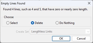
- Choose what to do as follows:
| To do this... | Do this... |
|---|---|
| Create a selection set of the features | Choose Select from the radio list and enter a name for the selection set in the Create Set editable drop-down list |
| Delete the features | Choose Delete from the radio list |
| Ignore the findings | Choose Do Nothing from the radio list |
- Click OK.
©2026 Caliper Corporation